Hi Frank,
The PWM output will be 3.3V LVTTL (actually only guaranteed to be 0.4V to 2.8V). Yes a transistor circuit would be required to change it to a 10V signal. Look at the PWM1KHz.c example.
Yes you can use a C program to do whatever calculations you require. But it isn't clear to me how your sensor works and if you can avoid positional drift if your frequencies are not exact. What is the physics behind the sensor arrangement.
Regards,
TK
| Group: DynoMotion |
Message: 4490 |
From: frank_19_88 |
Date: 4/4/2012 |
| Subject: Re: New challenge, high speed 1 - 100 Khz input and output |
Hi TK,
Tank you for your quick reply,
I am retrofitting a old milling machine, the encoders are from 1985 I think.
But it is a lot of work to replace them with new one's!
And I like building electronics more than changing hardware :)
The old controller can read the encoder position without drift, so I hope I can do it also.
The sensor needs an input trams (square wave) of 10 Khz.
If the encoder is moving to:
The left it give's a trams (square wave) of 4 Khz.
not moving it give's a trams (square wave) of 5 Khz.
The right it give's a trams (square wave) of 6 Khz.
At this point we can calculate our movement:
input trams / 2 - output trams = movement
I do need to find hardware which can convert the PWM signal to a TTL (with A&B) signal?
With kind regards,
Frank
--- In DynoMotion@yahoogroups.com, Tom Kerekes <tk@...> wrote:
>
> Hi Frank,
> Â
> The PWM output will be 3.3V LVTTL (actually only guaranteed to be 0.4V to 2.8V). Yes a transistor circuit would be required to change it to a 10V signal. Look at the PWM1KHz.c example.
> Â
> Yes you can use a C program to do whatever calculations you require. But it isn't clear to me how your sensor works and if you can avoid positional drift if your frequencies are not exact. What is the physics behind the sensor arrangement.
> Â
> Regards,
> TK
> Â
> Â
>
>
> ________________________________
> From: frank_19_88 <frank_19_88@...>
> To: DynoMotion@yahoogroups.com
> Sent: Wednesday, April 4, 2012 10:09 AM
> Subject: [DynoMotion] Re: New challenge, high speed 1 - 100 Khz input and output
>
>
> Â
> Hi TK,
>
> Thank you for your quick reply,
>
> I meant an square wave within the range of 1KHz till 100KHz.
>
> The PWM output give's a square wave of 3.3V or 5.0V? I can change that voltage with an transistor to 10V?
>
> I will try to make an 'RC delay' or a '2 bit gray scale counter' first because the old hardware can generate the pulses to test if the input is working.
>
> If I converted the signals to A B quadrature, is it possible to write a .C code to calculate the position.
> Or do I have to calculate the difference between de input and returned pulsses with the external hardware? And sent only the difference to the Kflop?
>
> Thank you,
>
> Frank
>
> --- In DynoMotion@yahoogroups.com, Tom Kerekes <tk@> wrote:
> >
> > Hi Frank,
> > ÃÂ
> > Sounds interesting but I don't really understand.
> > ÃÂ
> > What does 1-100 10KHz mean?
> > ÃÂ
> > KFLOP has 8-bit PWM generators that can generate a ~10KHz signal.ÃÂ Set the pre-scaler to ~6 to generate ~10KHz (16.67 MHz/256/6).
> > ÃÂ
> > Set the duty cycle to 128 for a square wave.
> > ÃÂ
> > But KFLOP doesn't have a means of counting pulses.ÃÂ It only can count A B quadrature.ÃÂ So you would need to convert the pulses to quadrature with an external circuit.ÃÂ RC delay might work.ÃÂ Or a 2 bit gray scale counter.
> > ÃÂ
> > Regards
> > TK
> >
> >
> > ________________________________
> > From: frank_19_88 <frank_19_88@>
> > To: DynoMotion@yahoogroups.com
> > Sent: Wednesday, April 4, 2012 7:43 AM
> > Subject: [DynoMotion] New challenge, high speed 1 - 100 Khz input and output
> >
> >
> >
> > ÃÂ
> >
> > Hi,
> >
> > For my latest project I want to use a 1 - 100 10KHz square wave signal 0 to 10 Vdc input and output to calculate the position of my axis.
> >
> > The idea is:
> > 1. Generate 10KHz square wave signal (with the Kflop, Kanalog, NE555 chip or an other chip)
> >
> > 2. The encoder give's me an 5KHz square wave signal 0 to 10 Vdc back.
> > (If the signal is 4KHz the axis is moving to the left and if the signal is 6KHz the axis is moving to the right)
> >
> > Challenge:
> > a. Is it possible to generate 10KHz 0-10V square wave signal with the Kanalog or Kflop? Do I need external hardware?
> >
> > b. Can I connect the 10Khz 0-10V square wave signal to the Kanalog or kflop? Do I need external hardware? (Maybe we need an chip to decrease the number of pules by 10 or 100?)
> >
> > c. Can I write an .C code which calculates the axis position every 90 us like:
> > axis = axis + (output pules/2 - input pulses) * 0.1 um
> >
> > Thank You,
> >
> > Frank
> >
> |
|
| Group: DynoMotion |
Message: 4491 |
From: frank_19_88 |
Date: 4/4/2012 |
| Subject: Re: New challenge, high speed 1 - 100 Khz input and output |
Oeps, I made a mistake, it is not a 'PWM signal to a TTL (with A&B) signal' it should be a 'pulse counter to a TTL (with A&B) signal converter'. I don't know which keywords I need use to search for that. Or do you know some hardware for that?
--- In DynoMotion@yahoogroups.com, "frank_19_88" <frank_19_88@...> wrote:
>
> Hi TK,
>
> Tank you for your quick reply,
>
> I am retrofitting a old milling machine, the encoders are from 1985 I think.
> But it is a lot of work to replace them with new one's!
>
> And I like building electronics more than changing hardware :)
>
> The old controller can read the encoder position without drift, so I hope I can do it also.
>
> The sensor needs an input trams (square wave) of 10 Khz.
> If the encoder is moving to:
> The left it give's a trams (square wave) of 4 Khz.
> not moving it give's a trams (square wave) of 5 Khz.
> The right it give's a trams (square wave) of 6 Khz.
>
> At this point we can calculate our movement:
> input trams / 2 - output trams = movement
>
> I do need to find hardware which can convert the PWM signal to a TTL (with A&B) signal?
>
> With kind regards,
>
> Frank
>
>
> --- In DynoMotion@yahoogroups.com, Tom Kerekes <tk@> wrote:
> >
> > Hi Frank,
> > Â
> > The PWM output will be 3.3V LVTTL (actually only guaranteed to be 0.4V to 2.8V). Yes a transistor circuit would be required to change it to a 10V signal. Look at the PWM1KHz.c example.
> > Â
> > Yes you can use a C program to do whatever calculations you require. But it isn't clear to me how your sensor works and if you can avoid positional drift if your frequencies are not exact. What is the physics behind the sensor arrangement.
> > Â
> > Regards,
> > TK
> > Â
> > Â
> >
> >
> > ________________________________
> > From: frank_19_88 <frank_19_88@>
> > To: DynoMotion@yahoogroups.com
> > Sent: Wednesday, April 4, 2012 10:09 AM
> > Subject: [DynoMotion] Re: New challenge, high speed 1 - 100 Khz input and output
> >
> >
> > Â
> > Hi TK,
> >
> > Thank you for your quick reply,
> >
> > I meant an square wave within the range of 1KHz till 100KHz.
> >
> > The PWM output give's a square wave of 3.3V or 5.0V? I can change that voltage with an transistor to 10V?
> >
> > I will try to make an 'RC delay' or a '2 bit gray scale counter' first because the old hardware can generate the pulses to test if the input is working.
> >
> > If I converted the signals to A B quadrature, is it possible to write a .C code to calculate the position.
> > Or do I have to calculate the difference between de input and returned pulsses with the external hardware? And sent only the difference to the Kflop?
> >
> > Thank you,
> >
> > Frank
> >
> > --- In DynoMotion@yahoogroups.com, Tom Kerekes <tk@> wrote:
> > >
> > > Hi Frank,
> > > ÃÂ
> > > Sounds interesting but I don't really understand.
> > > ÃÂ
> > > What does 1-100 10KHz mean?
> > > ÃÂ
> > > KFLOP has 8-bit PWM generators that can generate a ~10KHz signal.ÃÂ Set the pre-scaler to ~6 to generate ~10KHz (16.67 MHz/256/6).
> > > ÃÂ
> > > Set the duty cycle to 128 for a square wave.
> > > ÃÂ
> > > But KFLOP doesn't have a means of counting pulses.ÃÂ It only can count A B quadrature.ÃÂ So you would need to convert the pulses to quadrature with an external circuit.ÃÂ RC delay might work.ÃÂ Or a 2 bit gray scale counter.
> > > ÃÂ
> > > Regards
> > > TK
> > >
> > >
> > > ________________________________
> > > From: frank_19_88 <frank_19_88@>
> > > To: DynoMotion@yahoogroups.com
> > > Sent: Wednesday, April 4, 2012 7:43 AM
> > > Subject: [DynoMotion] New challenge, high speed 1 - 100 Khz input and output
> > >
> > >
> > >
> > > ÃÂ
> > >
> > > Hi,
> > >
> > > For my latest project I want to use a 1 - 100 10KHz square wave signal 0 to 10 Vdc input and output to calculate the position of my axis.
> > >
> > > The idea is:
> > > 1. Generate 10KHz square wave signal (with the Kflop, Kanalog, NE555 chip or an other chip)
> > >
> > > 2. The encoder give's me an 5KHz square wave signal 0 to 10 Vdc back.
> > > (If the signal is 4KHz the axis is moving to the left and if the signal is 6KHz the axis is moving to the right)
> > >
> > > Challenge:
> > > a. Is it possible to generate 10KHz 0-10V square wave signal with the Kanalog or Kflop? Do I need external hardware?
> > >
> > > b. Can I connect the 10Khz 0-10V square wave signal to the Kanalog or kflop? Do I need external hardware? (Maybe we need an chip to decrease the number of pules by 10 or 100?)
> > >
> > > c. Can I write an .C code which calculates the axis position every 90 us like:
> > > axis = axis + (output pules/2 - input pulses) * 0.1 um
> > >
> > > Thank You,
> > >
> > > Frank
> > >
> >
> |
|
| Group: DynoMotion |
Message: 4492 |
From: Tom Kerekes |
Date: 4/4/2012 |
| Subject: Re: New challenge, high speed 1 - 100 Khz input and output |
Hi Frank,
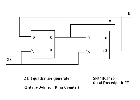
See attached for simple Quad generator.
Actually instad of using the PWM you could also use a Step/Dir Generator set to quadrature output mode. It can more exactly generate any frequency and also has the benefit of keeping count of exactly how may steps were made.
Regards
TK
| Group: DynoMotion |
Message: 4536 |
From: frank_19_88 |
Date: 4/10/2012 |
| Subject: Re: New challenge, high speed 1 - 100 Khz input and output |
Hi TK,
Thank you for the Quad generator.
Today I did create the PCB and would like to test it tomorrow.
The idea is:
1st: Generate about 10 khz with Step/Dir Generator.
2nd: Connect this signal to the Quad generator (clk) and connect the A,B, A not and B not signal to the 'JP1/JP2 Differential Inputs' of the Kanalog.
3th: Read the amount of pulses at the differential Input. (should be 1/4 the of the output because of the Quad generator)
I have al few questions for you:
A: How can I set the 10 khz at the Step output?
B: Wich Step output should I take? (Because JP5 And JP12 are connected to the Kanalog)
C: Is the Step output about 0V to 5V ?
D: What is the maxium frequention of the step output?
E: Do you have a .C program wich can count the amount of pulses at the differential Input?
I hope to test the PCB tomorrow :)
Thank you,
Frank
--- In DynoMotion@yahoogroups.com, Tom Kerekes <tk@...> wrote:
>
> Hi Frank,
> Â
> See attached for simple Quad generator.
> Â
> Actually instad of using the PWM you could also use a Step/Dir Generator set to quadrature output mode. It can more exactly generate any frequency and also has the benefit of keeping count of exactly how may steps were made.
> Â
> Regards
> TK
> Â
>
>
> ________________________________
> From: frank_19_88 <frank_19_88@...>
> To: DynoMotion@yahoogroups.com
> Sent: Wednesday, April 4, 2012 12:52 PM
> Subject: [DynoMotion] Re: New challenge, high speed 1 - 100 Khz input and output
>
>
> Â
> Hi TK,
>
> Tank you for your quick reply,
>
> I am retrofitting a old milling machine, the encoders are from 1985 I think.
> But it is a lot of work to replace them with new one's!
>
> And I like building electronics more than changing hardware :)
>
> The old controller can read the encoder position without drift, so I hope I can do it also.
>
> The sensor needs an input trams (square wave) of 10 Khz.
> If the encoder is moving to:
> The left it give's a trams (square wave) of 4 Khz.
> not moving it give's a trams (square wave) of 5 Khz.
> The right it give's a trams (square wave) of 6 Khz.
>
> At this point we can calculate our movement:
> input trams / 2 - output trams = movement
>
> I do need to find hardware which can convert the PWM signal to a TTL (with A&B) signal?
>
> With kind regards,
>
> Frank
>
> --- In DynoMotion@yahoogroups.com, Tom Kerekes <tk@> wrote:
> >
> > Hi Frank,
> > ÃÂ
> > The PWM output will be 3.3V LVTTL (actually only guaranteed to be 0.4V to 2.8V).ÃÂ Yes a transistor circuit would be required to change it to a 10V signal.ÃÂ Look at the PWM1KHz.c example.
> > ÃÂ
> > Yes you can use a C program to do whatever calculations you require.ÃÂ But it isn't clear to me how your sensor works and if you can avoid positional drift if your frequencies are not exact.ÃÂ What is the physics behind the sensor arrangement.
> > ÃÂ
> > Regards,
> > TK
> > ÃÂ
> > ÃÂ
> >
> >
> > ________________________________
> > From: frank_19_88 <frank_19_88@>
> > To: DynoMotion@yahoogroups.com
> > Sent: Wednesday, April 4, 2012 10:09 AM
> > Subject: [DynoMotion] Re: New challenge, high speed 1 - 100 Khz input and output
> >
> >
> > ÃÂ
> > Hi TK,
> >
> > Thank you for your quick reply,
> >
> > I meant an square wave within the range of 1KHz till 100KHz.
> >
> > The PWM output give's a square wave of 3.3V or 5.0V? I can change that voltage with an transistor to 10V?
> >
> > I will try to make an 'RC delay' or a '2 bit gray scale counter' first because the old hardware can generate the pulses to test if the input is working.
> >
> > If I converted the signals to A B quadrature, is it possible to write a .C code to calculate the position.
> > Or do I have to calculate the difference between de input and returned pulsses with the external hardware? And sent only the difference to the Kflop?
> >
> > Thank you,
> >
> > Frank
> >
> > --- In DynoMotion@yahoogroups.com, Tom Kerekes <tk@> wrote:
> > >
> > > Hi Frank,
> > > ÃâÃÂ
> > > Sounds interesting but I don't really understand.
> > > ÃâÃÂ
> > > What does 1-100 10KHz mean?
> > > ÃâÃÂ
> > > KFLOP has 8-bit PWM generators that can generate a ~10KHz signal.ÃâàSet the pre-scaler to ~6 to generate ~10KHz (16.67 MHz/256/6).
> > > ÃâÃÂ
> > > Set the duty cycle to 128 for a square wave.
> > > ÃâÃÂ
> > > But KFLOP doesn't have a means of counting pulses.ÃâàIt only can count A B quadrature.ÃâàSo you would need to convert the pulses to quadrature with an external circuit.ÃâàRC delay might work.ÃâàOr a 2 bit gray scale counter.
> > > ÃâÃÂ
> > > Regards
> > > TK
> > >
> > >
> > > ________________________________
> > > From: frank_19_88 <frank_19_88@>
> > > To: DynoMotion@yahoogroups.com
> > > Sent: Wednesday, April 4, 2012 7:43 AM
> > > Subject: [DynoMotion] New challenge, high speed 1 - 100 Khz input and output
> > >
> > >
> > >
> > > ÃâÃÂ
> > >
> > > Hi,
> > >
> > > For my latest project I want to use a 1 - 100 10KHz square wave signal 0 to 10 Vdc input and output to calculate the position of my axis.
> > >
> > > The idea is:
> > > 1. Generate 10KHz square wave signal (with the Kflop, Kanalog, NE555 chip or an other chip)
> > >
> > > 2. The encoder give's me an 5KHz square wave signal 0 to 10 Vdc back.
> > > (If the signal is 4KHz the axis is moving to the left and if the signal is 6KHz the axis is moving to the right)
> > >
> > > Challenge:
> > > a. Is it possible to generate 10KHz 0-10V square wave signal with the Kanalog or Kflop? Do I need external hardware?
> > >
> > > b. Can I connect the 10Khz 0-10V square wave signal to the Kanalog or kflop? Do I need external hardware? (Maybe we need an chip to decrease the number of pules by 10 or 100?)
> > >
> > > c. Can I write an .C code which calculates the axis position every 90 us like:
> > > axis = axis + (output pules/2 - input pulses) * 0.1 um
> > >
> > > Thank You,
> > >
> > > Frank
> > >
> >
> |
|
| Group: DynoMotion |
Message: 4537 |
From: Tom Kerekes |
Date: 4/10/2012 |
| Subject: Re: New challenge, high speed 1 - 100 Khz input and output |
Hi Frank,
I still don't understand how your sensor works. I think you may need to feed back both the original 10KHz signal and the signal modified by the encoder, then subtract them.
The simplest thing would be to configure a dummy axis as a Step/Dir axis. Then just tell it to Jog at 10000 (or 40000) steps/sec.
The simplest Step/Dir output to use would be from KFLOP JP5. This will disable the differential inputs on Kanalog JP2.
The Step/Dir outputs are 3.3V LVTTL signals (swings from less than 0.4V to more than 2.8V sourec and sink 16ma).
The max pulse rate of the Step/Dir Generators are 2.5MHz. You probably want to select quadrature output mode 2.5/4 MHz cycles per second.
I would configure the dummy axis as encoder input mode. The encoder count will then be chx->Position.
Regards
TK
| Group: DynoMotion |
Message: 4539 |
From: frank_19_88 |
Date: 4/11/2012 |
| Subject: Re: New challenge, high speed 1 - 100 Khz input and output |
Hi TK,
The sensor needs a input puls of 10 Khz to work.
The sensor has only 1 output: (it give's squire pulses)
when the output is 4Khz it means the sensor is moving to the left
1Khz = fast movement to left
5Khz = no movement
6Khz = movement to right
Today I did try to generate a puls signal with the Kflop.
I did connect my scope to JP5 pin 1 and to GND.
When I SET IO bit 36, I can see 1 puls on the scope.
But when I config a axis (see below) and set jog0=10000, nothing changes on the scope.
(puls length = 2.4 * 10^-7 and scope = 20mhz = 5*10^-8)
I don't understand what i am doing wrong :(
With kind regards,
Frank
ch0->InputMode=NO_INPUT_MODE;
ch0->OutputMode=STEP_DIR_MODE;
ch0->Vel=1.6e+006;
ch0->Accel=6e+006;
ch0->Jerk=2e+008;
ch0->P=1;
ch0->I=1;
ch0->D=1;
ch0->FFAccel=0;
ch0->FFVel=0;
ch0->MaxI=200;
ch0->MaxErr=1e+006;
ch0->MaxOutput=200;
ch0->DeadBandGain=1;
ch0->DeadBandRange=0;
ch0->InputChan0=0;
ch0->InputChan1=0;
ch0->OutputChan0=12;
ch0->OutputChan1=0;
ch0->MasterAxis=-1;
ch0->LimitSwitchOptions=0x0;
ch0->InputGain0=1;
ch0->InputGain1=1;
ch0->InputOffset0=0;
ch0->InputOffset1=0;
ch0->OutputGain=1;
ch0->OutputOffset=0;
ch0->SlaveGain=1;
ch0->BacklashMode=BACKLASH_OFF;
ch0->BacklashAmount=0;
ch0->BacklashRate=0;
ch0->invDistPerCycle=1;
ch0->Lead=0;
ch0->MaxFollowingError=1000000000;
ch0->StepperAmplitude=20;
ch0->iir[0].B0=1;
ch0->iir[0].B1=0;
ch0->iir[0].B2=0;
ch0->iir[0].A1=0;
ch0->iir[0].A2=0;
ch0->iir[1].B0=1;
ch0->iir[1].B1=0;
ch0->iir[1].B2=0;
ch0->iir[1].A1=0;
ch0->iir[1].A2=0;
ch0->iir[2].B0=0.000769;
ch0->iir[2].B1=0.001538;
ch0->iir[2].B2=0.000769;
ch0->iir[2].A1=1.92076;
ch0->iir[2].A2=-0.923833;
--- In DynoMotion@yahoogroups.com, Tom Kerekes <tk@...> wrote:
>
> Hi Frank,
> Â
> I still don't understand how your sensor works. I think you may need to feed back both the original 10KHz signal and the signal modified by the encoder, then subtract them.
> Â
> The simplest thing would be to configure a dummy axis as a Step/Dir axis. Then just tell it to Jog at 10000 (or 40000) steps/sec.
> Â
> The simplest Step/Dir output to use would be from KFLOP JP5. This will disable the differential inputs on Kanalog JP2.
> Â
> The Step/Dir outputs are 3.3V LVTTL signals (swings from less than 0.4V to more than 2.8V sourec and sink 16ma).
> Â
> The max pulse rate of the Step/Dir Generators are 2.5MHz. You probably want to select quadrature output mode 2.5/4 MHz cycles per second.
> Â
> I would configure the dummy axis as encoder input mode. The encoder count will then be chx->Position.
> Â
> Regards
> TK
> Â
>
> From: frank_19_88 <frank_19_88@...>
> To: DynoMotion@yahoogroups.com
> Sent: Tuesday, April 10, 2012 1:22 PM
> Subject: [DynoMotion] Re: New challenge, high speed 1 - 100 Khz input and output
>
>
> Â
> Hi TK,
>
> Thank you for the Quad generator.
>
> Today I did create the PCB and would like to test it tomorrow.
> The idea is:
> 1st: Generate about 10 khz with Step/Dir Generator.
> 2nd: Connect this signal to the Quad generator (clk) and connect the A,B, A not and B not signal to the 'JP1/JP2 Differential Inputs' of the Kanalog.
> 3th: Read the amount of pulses at the differential Input. (should be 1/4 the of the output because of the Quad generator)
>
> I have al few questions for you:
> A: How can I set the 10 khz at the Step output?
> B: Wich Step output should I take? (Because JP5 And JP12 are connected to the Kanalog)
> C: Is the Step output about 0V to 5V ?
> D: What is the maxium frequention of the step output?
>
> E: Do you have a .C program wich can count the amount of pulses at the differential Input?
>
> I hope to test the PCB tomorrow :)
>
> Thank you,
>
> Frank
>
> --- In DynoMotion@yahoogroups.com, Tom Kerekes <tk@> wrote:
> >
> > Hi Frank,
> > ÃÂ
> > See attached for simple Quad generator.
> > ÃÂ
> > Actually instad of using the PWM you could also use a Step/Dir Generator set to quadrature output mode.ÃÂ It can more exactly generate any frequency and also has the benefit of keeping count of exactly how may steps were made.
> > ÃÂ
> > Regards
> > TK
> > ÃÂ
> >
> >
> > ________________________________
> > From: frank_19_88 <frank_19_88@>
> > To: DynoMotion@yahoogroups.com
> > Sent: Wednesday, April 4, 2012 12:52 PM
> > Subject: [DynoMotion] Re: New challenge, high speed 1 - 100 Khz input and output
> >
> >
> > ÃÂ
> > Hi TK,
> >
> > Tank you for your quick reply,
> >
> > I am retrofitting a old milling machine, the encoders are from 1985 I think.
> > But it is a lot of work to replace them with new one's!
> >
> > And I like building electronics more than changing hardware :)
> >
> > The old controller can read the encoder position without drift, so I hope I can do it also.
> >
> > The sensor needs an input trams (square wave) of 10 Khz.
> > If the encoder is moving to:
> > The left it give's a trams (square wave) of 4 Khz.
> > not moving it give's a trams (square wave) of 5 Khz.
> > The right it give's a trams (square wave) of 6 Khz.
> >
> > At this point we can calculate our movement:
> > input trams / 2 - output trams = movement
> >
> > I do need to find hardware which can convert the PWM signal to a TTL (with A&B) signal?
> >
> > With kind regards,
> >
> > Frank
> >
> > --- In DynoMotion@yahoogroups.com, Tom Kerekes <tk@> wrote:
> > >
> > > Hi Frank,
> > > ÃâÃÂ
> > > The PWM output will be 3.3V LVTTL (actually only guaranteed to be 0.4V to 2.8V).ÃâàYes a transistor circuit would be required to change it to a 10V signal.ÃâàLook at the PWM1KHz.c example.
> > > ÃâÃÂ
> > > Yes you can use a C program to do whatever calculations you require.ÃâàBut it isn't clear to me how your sensor works and if you can avoid positional drift if your frequencies are not exact.ÃâàWhat is the physics behind the sensor arrangement.
> > > ÃâÃÂ
> > > Regards,
> > > TK
> > > ÃâÃÂ
> > > ÃâÃÂ
> > >
> > >
> > > ________________________________
> > > From: frank_19_88 <frank_19_88@>
> > > To: DynoMotion@yahoogroups.com
> > > Sent: Wednesday, April 4, 2012 10:09 AM
> > > Subject: [DynoMotion] Re: New challenge, high speed 1 - 100 Khz input and output
> > >
> > >
> > > ÃâÃÂ
> > > Hi TK,
> > >
> > > Thank you for your quick reply,
> > >
> > > I meant an square wave within the range of 1KHz till 100KHz.
> > >
> > > The PWM output give's a square wave of 3.3V or 5.0V? I can change that voltage with an transistor to 10V?
> > >
> > > I will try to make an 'RC delay' or a '2 bit gray scale counter' first because the old hardware can generate the pulses to test if the input is working.
> > >
> > > If I converted the signals to A B quadrature, is it possible to write a .C code to calculate the position.
> > > Or do I have to calculate the difference between de input and returned pulsses with the external hardware? And sent only the difference to the Kflop?
> > >
> > > Thank you,
> > >
> > > Frank
> > >
> > > --- In DynoMotion@yahoogroups.com, Tom Kerekes <tk@> wrote:
> > > >
> > > > Hi Frank,
> > > > ÃÆ'ââ¬Å¡ÃâÃÂ
> > > > Sounds interesting but I don't really understand.
> > > > ÃÆ'ââ¬Å¡ÃâÃÂ
> > > > What does 1-100 10KHz mean?
> > > > ÃÆ'ââ¬Å¡ÃâÃÂ
> > > > KFLOP has 8-bit PWM generators that can generate a ~10KHz signal.ÃÆ'ââ¬Å¡ÃâàSet the pre-scaler to ~6 to generate ~10KHz (16.67 MHz/256/6).
> > > > ÃÆ'ââ¬Å¡ÃâÃÂ
> > > > Set the duty cycle to 128 for a square wave.
> > > > ÃÆ'ââ¬Å¡ÃâÃÂ
> > > > But KFLOP doesn't have a means of counting pulses.ÃÆ'ââ¬Å¡ÃâàIt only can count A B quadrature.ÃÆ'ââ¬Å¡ÃâàSo you would need to convert the pulses to quadrature with an external circuit.ÃÆ'ââ¬Å¡ÃâàRC delay might work.ÃÆ'ââ¬Å¡ÃâàOr a 2 bit gray scale counter.
> > > > ÃÆ'ââ¬Å¡ÃâÃÂ
> > > > Regards
> > > > TK
> > > >
> > > >
> > > > ________________________________
> > > > From: frank_19_88 <frank_19_88@>
> > > > To: DynoMotion@yahoogroups.com
> > > > Sent: Wednesday, April 4, 2012 7:43 AM
> > > > Subject: [DynoMotion] New challenge, high speed 1 - 100 Khz input and output
> > > >
> > > >
> > > >
> > > > ÃÆ'ââ¬Å¡ÃâÃÂ
> > > >
> > > > Hi,
> > > >
> > > > For my latest project I want to use a 1 - 100 10KHz square wave signal 0 to 10 Vdc input and output to calculate the position of my axis.
> > > >
> > > > The idea is:
> > > > 1. Generate 10KHz square wave signal (with the Kflop, Kanalog, NE555 chip or an other chip)
> > > >
> > > > 2. The encoder give's me an 5KHz square wave signal 0 to 10 Vdc back.
> > > > (If the signal is 4KHz the axis is moving to the left and if the signal is 6KHz the axis is moving to the right)
> > > >
> > > > Challenge:
> > > > a. Is it possible to generate 10KHz 0-10V square wave signal with the Kanalog or Kflop? Do I need external hardware?
> > > >
> > > > b. Can I connect the 10Khz 0-10V square wave signal to the Kanalog or kflop? Do I need external hardware? (Maybe we need an chip to decrease the number of pules by 10 or 100?)
> > > >
> > > > c. Can I write an .C code which calculates the axis position every 90 us like:
> > > > axis = axis + (output pules/2 - input pulses) * 0.1 um
> > > >
> > > > Thank You,
> > > >
> > > > Frank
> > > >
> > >
> >
> |
|
| Group: DynoMotion |
Message: 4540 |
From: TK |
Date: 4/11/2012 |
| Subject: Re: New challenge, high speed 1 - 100 Khz input and output |
Hi Frank,
I understand the basic concept but not how you can avoid slow position drift. Unless you do a subtraction of the accumulated 10KHz base frequency/2
Your initialization code looks correct. After you jog the axis look at the Axis Screen. Is the axis enabled? Is the Destination changing?
Regards
TK
Hi TK,
The sensor needs a input puls of 10 Khz to work.
The sensor has only 1 output: (it give's squire pulses)
when the output is 4Khz it means the sensor is moving to the left
1Khz = fast movement to left
5Khz = no movement
6Khz = movement to right
Today I did try to generate a puls signal with the Kflop.
I did connect my scope to JP5 pin 1 and to GND.
When I SET IO bit 36, I can see 1 puls on the scope.
But when I config a axis (see below) and set jog0=10000, nothing changes on the scope.
(puls length = 2.4 * 10^-7 and scope = 20mhz = 5*10^-8)
I don't understand what i am doing wrong :(
With kind regards,
Frank
ch0->InputMode=NO_INPUT_MODE;
ch0->OutputMode=STEP_DIR_MODE;
ch0->Vel=1.6e+006;
ch0->Accel=6e+006;
ch0->Jerk=2e+008;
ch0->P=1;
ch0->I=1;
ch0->D=1;
ch0->FFAccel=0;
ch0->FFVel=0;
ch0->MaxI=200;
ch0->MaxErr=1e+006;
ch0->MaxOutput=200;
ch0->DeadBandGain=1;
ch0->DeadBandRange=0;
ch0->InputChan0=0;
ch0->InputChan1=0;
ch0->OutputChan0=12;
ch0->OutputChan1=0;
ch0->MasterAxis=-1;
ch0->LimitSwitchOptions=0x0;
ch0->InputGain0=1;
ch0->InputGain1=1;
ch0->InputOffset0=0;
ch0->InputOffset1=0;
ch0->OutputGain=1;
ch0->OutputOffset=0;
ch0->SlaveGain=1;
ch0->BacklashMode=BACKLASH_OFF;
ch0->BacklashAmount=0;
ch0->BacklashRate=0;
ch0->invDistPerCycle=1;
ch0->Lead=0;
ch0->MaxFollowingError=1000000000;
ch0->StepperAmplitude=20;
ch0->iir[0].B0=1;
ch0->iir[0].B1=0;
ch0->iir[0].B2=0;
ch0->iir[0].A1=0;
ch0->iir[0].A2=0;
ch0->iir[1].B0=1;
ch0->iir[1].B1=0;
ch0->iir[1].B2=0;
ch0->iir[1].A1=0;
ch0->iir[1].A2=0;
ch0->iir[2].B0=0.000769;
ch0->iir[2].B1=0.001538;
ch0->iir[2].B2=0.000769;
ch0->iir[2].A1=1.92076;
ch0->iir[2].A2=-0.923833;
--- In DynoMotion@yahoogroups.com, Tom Kerekes <tk@...> wrote:
>
> Hi Frank,
> Â
> I still don't understand how your sensor works. I think you may need to feed back both the original 10KHz signal and the signal modified by the encoder, then subtract them.
> Â
> The simplest thing would be to configure a dummy axis as a Step/Dir axis. Then just tell it to Jog at 10000 (or 40000) steps/sec.
> Â
> The simplest Step/Dir output to use would be from KFLOP JP5. This will disable the differential inputs on Kanalog JP2.
> Â
> The Step/Dir outputs are 3.3V LVTTL signals (swings from less than 0.4V to more than 2.8V sourec and sink 16ma).
> Â
> The max pulse rate of the Step/Dir Generators are 2.5MHz. You probably want to select quadrature output mode 2.5/4 MHz cycles per second.
> Â
> I would configure the dummy axis as encoder input mode. The encoder count will then be chx->Position.
> Â
> Regards
> TK
> Â
>
> From: frank_19_88 <frank_19_88@...>
> To: DynoMotion@yahoogroups.com
> Sent: Tuesday, April 10, 2012 1:22 PM
> Subject: [DynoMotion] Re: New challenge, high speed 1 - 100 Khz input and output
>
>
> Â
> Hi TK,
>
> Thank you for the Quad generator.
>
> Today I did create the PCB and would like to test it tomorrow.
> The idea is:
> 1st: Generate about 10 khz with Step/Dir Generator.
> 2nd: Connect this signal to the Quad generator (clk) and connect the A,B, A not and B not signal to the 'JP1/JP2 Differential Inputs' of the Kanalog.
> 3th: Read the amount of pulses at the differential Input. (should be 1/4 the of the output because of the Quad generator)
>
> I have al few questions for you:
> A: How can I set the 10 khz at the Step output?
> B: Wich Step output should I take? (Because JP5 And JP12 are connected to the Kanalog)
> C: Is the Step output about 0V to 5V ?
> D: What is the maxium frequention of the step output?
>
> E: Do you have a .C program wich can count the amount of pulses at the differential Input?
>
> I hope to test the PCB tomorrow :)
>
> Thank you,
>
> Frank
>
> --- In DynoMotion@yahoogroups.com, Tom Kerekes <tk@> wrote:
> >
> > Hi Frank,
> > ÂÂ
> > See attached for simple Quad generator.
> > ÂÂ
> > Actually instad of using the PWM you could also use a Step/Dir Generator set to quadrature output mode. It can more exactly generate any frequency and also has the benefit of keeping count of exactly how may steps were made.
> > ÂÂ
> > Regards
> > TK
> > ÂÂ
> >
> >
> > ________________________________
> > From: frank_19_88 <frank_19_88@>
> > To: DynoMotion@yahoogroups.com
> > Sent: Wednesday, April 4, 2012 12:52 PM
> > Subject: [DynoMotion] Re: New challenge, high speed 1 - 100 Khz input and output
> >
> >
> > ÂÂ
> > Hi TK,
> >
> > Tank you for your quick reply,
> >
> > I am retrofitting a old milling machine, the encoders are from 1985 I think.
> > But it is a lot of work to replace them with new one's!
> >
> > And I like building electronics more than changing hardware :)
> >
> > The old controller can read the encoder position without drift, so I hope I can do it also.
> >
> > The sensor needs an input trams (square wave) of 10 Khz.
> > If the encoder is moving to:
> > The left it give's a trams (square wave) of 4 Khz.
> > not moving it give's a trams (square wave) of 5 Khz.
> > The right it give's a trams (square wave) of 6 Khz.
> >
> > At this point we can calculate our movement:
> > input trams / 2 - output trams = movement
> >
> > I do need to find hardware which can convert the PWM signal to a TTL (with A&B) signal?
> >
> > With kind regards,
> >
> > Frank
> >
> > --- In DynoMotion@yahoogroups.com, Tom Kerekes <tk@> wrote:
> > >
> > > Hi Frank,
> > > ÂÂÂ
> > > The PWM output will be 3.3V LVTTL (actually only guaranteed to be 0.4V to 2.8V). Yes a transistor circuit would be required to change it to a 10V signal. Look at the PWM1KHz.c example.
> > > ÂÂÂ
> > > Yes you can use a C program to do whatever calculations you require. But it isn't clear to me how your sensor works and if you can avoid positional drift if your frequencies are not exact. What is the physics behind the sensor arrangement.
> > > ÂÂÂ
> > > Regards,
> > > TK
> > > ÂÂÂ
> > > ÂÂÂ
> > >
> > >
> > > ________________________________
> > > From: frank_19_88 <frank_19_88@>
> > > To: DynoMotion@yahoogroups.com
> > > Sent: Wednesday, April 4, 2012 10:09 AM
> > > Subject: [DynoMotion] Re: New challenge, high speed 1 - 100 Khz input and output
> > >
> > >
> > > ÂÂÂ
> > > Hi TK,
> > >
> > > Thank you for your quick reply,
> > >
> > > I meant an square wave within the range of 1KHz till 100KHz.
> > >
> > > The PWM output give's a square wave of 3.3V or 5.0V? I can change that voltage with an transistor to 10V?
> > >
> > > I will try to make an 'RC delay' or a '2 bit gray scale counter' first because the old hardware can generate the pulses to test if the input is working.
> > >
> > > If I converted the signals to A B quadrature, is it possible to write a .C code to calculate the position.
> > > Or do I have to calculate the difference between de input and returned pulsses with the external hardware? And sent only the difference to the Kflop?
> > >
> > > Thank you,
> > >
> > > Frank
> > >
> > > --- In DynoMotion@yahoogroups.com, Tom Kerekes <tk@> wrote:
> > > >
> > > > Hi Frank,
> > > > ÃÆ'‚ÂÂÂ
> > > > Sounds interesting but I don't really understand.
> > > > ÃÆ'‚ÂÂÂ
> > > > What does 1-100 10KHz mean?
> > > > ÃÆ'‚ÂÂÂ
> > > > KFLOP has 8-bit PWM generators that can generate a ~10KHz signal.ÃÆ'‚ Set the pre-scaler to ~6 to generate ~10KHz (16.67 MHz/256/6).
> > > > ÃÆ'‚ÂÂÂ
> > > > Set the duty cycle to 128 for a square wave.
> > > > ÃÆ'‚ÂÂÂ
> > > > But KFLOP doesn't have a means of counting pulses.ÃÆ'‚ It only can count A B quadrature.ÃÆ'‚ So you would need to convert the pulses to quadrature with an external circuit.ÃÆ'‚ RC delay might work.ÃÆ'‚ Or a 2 bit gray scale counter.
> > > > ÃÆ'‚ÂÂÂ
> > > > Regards
> > > > TK
> > > >
> > > >
> > > > ________________________________
> > > > From: frank_19_88 <frank_19_88@>
> > > > To: DynoMotion@yahoogroups.com
> > > > Sent: Wednesday, April 4, 2012 7:43 AM
> > > > Subject: [DynoMotion] New challenge, high speed 1 - 100 Khz input and output
> > > >
> > > >
> > > >
> > > > ÃÆ'‚ÂÂÂ
> > > >
> > > > Hi,
> > > >
> > > > For my latest project I want to use a 1 - 100 10KHz square wave signal 0 to 10 Vdc input and output to calculate the position of my axis.
> > > >
> > > > The idea is:
> > > > 1. Generate 10KHz square wave signal (with the Kflop, Kanalog, NE555 chip or an other chip)
> > > >
> > > > 2. The encoder give's me an 5KHz square wave signal 0 to 10 Vdc back.
> > > > (If the signal is 4KHz the axis is moving to the left and if the signal is 6KHz the axis is moving to the right)
> > > >
> > > > Challenge:
> > > > a. Is it possible to generate 10KHz 0-10V square wave signal with the Kanalog or Kflop? Do I need external hardware?
> > > >
> > > > b. Can I connect the 10Khz 0-10V square wave signal to the Kanalog or kflop? Do I need external hardware? (Maybe we need an chip to decrease the number of pules by 10 or 100?)
> > > >
> > > > c. Can I write an .C code which calculates the axis position every 90 us like:
> > > > axis = axis + (output pules/2 - input pulses) * 0.1 um
> > > >
> > > > Thank You,
> > > >
> > > > Frank
> > > >
> > >
> >
>
|
|
| Group: DynoMotion |
Message: 4544 |
From: frank_19_88 |
Date: 4/11/2012 |
| Subject: Re: New challenge, high speed 1 - 100 Khz input and output |
Hi TK,
Yes, I wand/need to subtract the base frequention.(the 10 khz never change!)
Yes, the axis destination is changing. The position (ofcourse) isn`t changing.
I did use a brand new kflop for the test. But didn`t update the flash. maybe that is the problem?
Thank you,
Frank
--- In DynoMotion@yahoogroups.com, TK <tk@...> wrote:
>
> Hi Frank,
>
> I understand the basic concept but not how you can avoid slow position drift. Unless you do a subtraction of the accumulated 10KHz base frequency/2
>
> Your initialization code looks correct. After you jog the axis look at the Axis Screen. Is the axis enabled? Is the Destination changing?
>
> Regards
>
> TK
>
> On Apr 11, 2012, at 4:39 AM, "frank_19_88" <frank_19_88@...> wrote:
>
> > Hi TK,
> >
> > The sensor needs a input puls of 10 Khz to work.
> > The sensor has only 1 output: (it give's squire pulses)
> > when the output is 4Khz it means the sensor is moving to the left
> > 1Khz = fast movement to left
> > 5Khz = no movement
> > 6Khz = movement to right
> >
> > Today I did try to generate a puls signal with the Kflop.
> > I did connect my scope to JP5 pin 1 and to GND.
> >
> > When I SET IO bit 36, I can see 1 puls on the scope.
> > But when I config a axis (see below) and set jog0=10000, nothing changes on the scope.
> > (puls length = 2.4 * 10^-7 and scope = 20mhz = 5*10^-8)
> >
> > I don't understand what i am doing wrong :(
> >
> > With kind regards,
> >
> > Frank
> >
> > ch0->InputMode=NO_INPUT_MODE;
> > ch0->OutputMode=STEP_DIR_MODE;
> > ch0->Vel=1.6e+006;
> > ch0->Accel=6e+006;
> > ch0->Jerk=2e+008;
> > ch0->P=1;
> > ch0->I=1;
> > ch0->D=1;
> > ch0->FFAccel=0;
> > ch0->FFVel=0;
> > ch0->MaxI=200;
> > ch0->MaxErr=1e+006;
> > ch0->MaxOutput=200;
> > ch0->DeadBandGain=1;
> > ch0->DeadBandRange=0;
> > ch0->InputChan0=0;
> > ch0->InputChan1=0;
> > ch0->OutputChan0=12;
> > ch0->OutputChan1=0;
> > ch0->MasterAxis=-1;
> > ch0->LimitSwitchOptions=0x0;
> > ch0->InputGain0=1;
> > ch0->InputGain1=1;
> > ch0->InputOffset0=0;
> > ch0->InputOffset1=0;
> > ch0->OutputGain=1;
> > ch0->OutputOffset=0;
> > ch0->SlaveGain=1;
> > ch0->BacklashMode=BACKLASH_OFF;
> > ch0->BacklashAmount=0;
> > ch0->BacklashRate=0;
> > ch0->invDistPerCycle=1;
> > ch0->Lead=0;
> > ch0->MaxFollowingError=1000000000;
> > ch0->StepperAmplitude=20;
> >
> > ch0->iir[0].B0=1;
> > ch0->iir[0].B1=0;
> > ch0->iir[0].B2=0;
> > ch0->iir[0].A1=0;
> > ch0->iir[0].A2=0;
> >
> > ch0->iir[1].B0=1;
> > ch0->iir[1].B1=0;
> > ch0->iir[1].B2=0;
> > ch0->iir[1].A1=0;
> > ch0->iir[1].A2=0;
> >
> > ch0->iir[2].B0=0.000769;
> > ch0->iir[2].B1=0.001538;
> > ch0->iir[2].B2=0.000769;
> > ch0->iir[2].A1=1.92076;
> > ch0->iir[2].A2=-0.923833;
> >
> > --- In DynoMotion@yahoogroups.com>
> > > To: DynoMotion@yahoogroups.com
> > > Sent: Tuesday, April 10, 2012 1:22 PM
> > > Subject: [DynoMotion] Re: New challenge, high speed 1 - 100 Khz input and output
> > >
> > >
> > > Ã
> > > Hi TK,
> > >
> > > Thank you for the Quad generator.
> > >
> > > Today I did create the PCB and would like to test it tomorrow.
> > > The idea is:
> > > 1st: Generate about 10 khz with Step/Dir Generator.
> > > 2nd: Connect this signal to the Quad generator (clk) and connect the A,B, A not and B not signal to the 'JP1/JP2 Differential Inputs' of the Kanalog.
> > > 3th: Read the amount of pulses at the differential Input. (should be 1/4 the of the output because of the Quad generator)
> > >
> > > I have al few questions for you:
> > > A: How can I set the 10 khz at the Step output?
> > > B: Wich Step output should I take? (Because JP5 And JP12 are connected to the Kanalog)
> > > C: Is the Step output about 0V to 5V ?
> > > D: What is the maxium frequention of the step output?
> > >
> > > E: Do you have a .C program wich can count the amount of pulses at the differential Input?
> > >
> > > I hope to test the PCB tomorrow :)
> > >
> > > Thank you,
> > >
> > > Frank
> > >
> > > --- In DynoMotion@yahoogroups.com>
> > > > To: DynoMotion@yahoogroups.com
> > > > Sent: Wednesday, April 4, 2012 12:52 PM
> > > > Subject: [DynoMotion] Re: New challenge, high speed 1 - 100 Khz input and output
> > > >
> > > >
> > > > ÃâÃ
> > > > Hi TK,
> > > >
> > > > Tank you for your quick reply,
> > > >
> > > > I am retrofitting a old milling machine, the encoders are from 1985 I think.
> > > > But it is a lot of work to replace them with new one's!
> > > >
> > > > And I like building electronics more than changing hardware :)
> > > >
> > > > The old controller can read the encoder position without drift, so I hope I can do it also.
> > > >
> > > > The sensor needs an input trams (square wave) of 10 Khz.
> > > > If the encoder is moving to:
> > > > The left it give's a trams (square wave) of 4 Khz.
> > > > not moving it give's a trams (square wave) of 5 Khz.
> > > > The right it give's a trams (square wave) of 6 Khz.
> > > >
> > > > At this point we can calculate our movement:
> > > > input trams / 2 - output trams = movement
> > > >
> > > > I do need to find hardware which can convert the PWM signal to a TTL (with A&B) signal?
> > > >
> > > > With kind regards,
> > > >
> > > > Frank
> > > >
> > > > --- In DynoMotion@yahoogroups.com>
> > > > > To: DynoMotion@yahoogroups.com
> > > > > Sent: Wednesday, April 4, 2012 10:09 AM
> > > > > Subject: [DynoMotion] Re: New challenge, high speed 1 - 100 Khz input and output
> > > > >
> > > > >
> > > > > ÃÆ'ââ¬Å¡ÃâÃ
> > > > > Hi TK,
> > > > >
> > > > > Thank you for your quick reply,
> > > > >
> > > > > I meant an square wave within the range of 1KHz till 100KHz.
> > > > >
> > > > > The PWM output give's a square wave of 3.3V or 5.0V? I can change that voltage with an transistor to 10V?
> > > > >
> > > > > I will try to make an 'RC delay' or a '2 bit gray scale counter' first because the old hardware can generate the pulses to test if the input is working.
> > > > >
> > > > > If I converted the signals to A B quadrature, is it possible to write a .C code to calculate the position.
> > > > > Or do I have to calculate the difference between de input and returned pulsses with the external hardware? And sent only the difference to the Kflop?
> > > > >
> > > > > Thank you,
> > > > >
> > > > > Frank
> > > > >
> > > > > --- In DynoMotion@yahoogroups.com>
> > > > > > To: DynoMotion@yahoogroups.com
> > > > > > Sent: Wednesday, April 4, 2012 7:43 AM
> > > > > > Subject: [DynoMotion] New challenge, high speed 1 - 100 Khz input and output
> > > > > >
> > > > > >
> > > > > >
> > > > > > ÃÆ'Ã'âââ¬Ã
¡ÃÆ'ââ¬Å¡ÃâÃ
> > > > > >
> > > > > > Hi,
> > > > > >
> > > > > > For my latest project I want to use a 1 - 100 10KHz square wave signal 0 to 10 Vdc input and output to calculate the position of my axis.
> > > > > >
> > > > > > The idea is:
> > > > > > 1. Generate 10KHz square wave signal (with the Kflop, Kanalog, NE555 chip or an other chip)
> > > > > >
> > > > > > 2. The encoder give's me an 5KHz square wave signal 0 to 10 Vdc back.
> > > > > > (If the signal is 4KHz the axis is moving to the left and if the signal is 6KHz the axis is moving to the right)
> > > > > >
> > > > > > Challenge:
> > > > > > a. Is it possible to generate 10KHz 0-10V square wave signal with the Kanalog or Kflop? Do I need external hardware?
> > > > > >
> > > > > > b. Can I connect the 10Khz 0-10V square wave signal to the Kanalog or kflop? Do I need external hardware? (Maybe we need an chip to decrease the number of pules by 10 or 100?)
> > > > > >
> > > > > > c. Can I write an .C code which calculates the axis position every 90 us like:
> > > > > > axis = axis + (output pules/2 - input pulses) * 0.1 um
> > > > > >
> > > > > > Thank You,
> > > > > >
> > > > > > Frank
> > > > > >
> > > > >
> > > >
> > >
> >
> >
> |
|
| Group: DynoMotion |
Message: 4546 |
From: Tom Kerekes |
Date: 4/11/2012 |
| Subject: Re: New challenge, high speed 1 - 100 Khz input and output |
Hi Frank,
I don't think a 10KHz generator (or the measurement period) can ever be exact. So there will always be some small error that will accumulate. I think you will need to measure the 10KHz in parallel with the other frequency to avoid this issue.
Hmmm I can't see why you aren't seeing pulses. No you should never update the Flash (Always let the Init.c program configure the board). Maybe that is the problem do you have a different configuration flashed in the board where a different Axis is also configured to use the same Step/Dir generator? Try:
#1 Flashing "New Version" and cycling KFLOP power so it is in the default state.
#2 Run your Init.c
#3 On console screen enter "Enable0" (Note that IO36 and 37 have been set as outputs)
#4 On Console screen enter "Jog0=10000"
Also adding 16 to the OutputChan0 value (change 12 to 28) will select the quadrature output mode so that instead of seeing 2us pulses you should see a 2.5KHz square wave.
Regards
TK
| Group: DynoMotion |
Message: 4611 |
From: frank_19_88 |
Date: 4/22/2012 |
| Subject: Re: New challenge, high speed 1 - 100 Khz input and output |
Hi TK,
Thank you for your replay,
The PCB I did create works perfect, I can measure the amount of pulses perfectly.
But the frequency of the pulses don't change when I move the encoder.
After flashing the new version, Step output 5 works good :)
I did find the drawing of the inside of the encoder:
http://www.freebits.nl/images/9603.png
MS = the measure signal
SC = 15,75 KHZ scan signal
RS = 1,575 KHZ reset signal (1/10 of scan)
The output pulse frequency don't change but give this kind of signal:
http://www.freebits.nl/images/7011.png (pin 14 of OQ005)(I think voltage is between 0 and 8,2V)
I also find the old (from 1990) electrical drawing witch can read the encoder(OQ005) signal.
It has a sample and hold ic, and convert it to an sine wave. (the khz should say something about the movement of the encoder)
http://www.freebits.nl/images/4952.png (15,75khz sample speed)
Should I copy the this PCB 1 on 1? And connect it to the ADC input? (Should be possible with the 90us sample rate)
Or is there at the moment an better way to filter the signal and connect it to my Kanalog? (Maybe with an faster sample rate)
Ps. I don't know where to buy the NE5537 anymore.
Hope you can help me to find an good solution,
Frank
--- In DynoMotion@yahoogroups.com, Tom Kerekes <tk@...> wrote:
>
> Hi Frank,
> Â
> I don't think a 10KHz generator (or the measurement period) can ever be exact. So there will always be some small error that will accumulate. I think you will need to measure the 10KHz in parallel with the other frequency to avoid this issue.
> Â
> Hmmm I can't see why you aren't seeing pulses. No you should never update the Flash (Always let the Init.c program configure the board). Maybe that is the problem do you have a different configuration flashed in the board where a different Axis is also configured to use the same Step/Dir generator? Try:
> Â
> #1Â Flashing "New Version" and cycling KFLOP power so it is in the default state.
> Â
> #2Run your Init.c
> Â
> #3 On console screen enter "Enable0"Â (Note that IO36 and 37 have been set as outputs)
> Â
> #4 On Console screen enter "Jog0=10000"
> Â
> Â
> Also adding 16 to the OutputChan0 value (change 12 to 28) will select the quadrature output mode so that instead of seeing 2us pulses you should see a 2.5KHz square wave.
> Â
> Â
> Regards
> TK
>
> From: frank_19_88 <frank_19_88@...>
> To: DynoMotion@yahoogroups.com
> Sent: Wednesday, April 11, 2012 8:50 AM
> Subject: [DynoMotion] Re: New challenge, high speed 1 - 100 Khz input and output
>
>
> Â
> Hi TK,
>
> Yes, I wand/need to subtract the base frequention.(the 10 khz never change!)
>
> Yes, the axis destination is changing. The position (ofcourse) isn`t changing.
>
> I did use a brand new kflop for the test. But didn`t update the flash. maybe that is the problem?
>
> Thank you,
>
> Frank
>
> --- In DynoMotion@yahoogroups.com, TK <tk@> wrote:
> >
> > Hi Frank,
> >
> > I understand the basic concept but not how you can avoid slow position drift. Unless you do a subtraction of the accumulated 10KHz base frequency/2
> >
> > Your initialization code looks correct. After you jog the axis look at the Axis Screen. Is the axis enabled? Is the Destination changing?
> >
> > Regards
> >
> > TK
> >
> > On Apr 11, 2012, at 4:39 AM, "frank_19_88" <frank_19_88@> wrote:
> >
> > > Hi TK,
> > >
> > > The sensor needs a input puls of 10 Khz to work.
> > > The sensor has only 1 output: (it give's squire pulses)
> > > when the output is 4Khz it means the sensor is moving to the left
> > > 1Khz = fast movement to left
> > > 5Khz = no movement
> > > 6Khz = movement to right
> > >
> > > Today I did try to generate a puls signal with the Kflop.
> > > I did connect my scope to JP5 pin 1 and to GND.
> > >
> > > When I SET IO bit 36, I can see 1 puls on the scope.
> > > But when I config a axis (see below) and set jog0=10000, nothing changes on the scope.
> > > (puls length = 2.4 * 10^-7 and scope = 20mhz = 5*10^-8)
> > >
> > > I don't understand what i am doing wrong :(
> > >
> > > With kind regards,
> > >
> > > Frank
> > >
> > > ch0->InputMode=NO_INPUT_MODE;
> > > ch0->OutputMode=STEP_DIR_MODE;
> > > ch0->Vel=1.6e+006;
> > > ch0->Accel=6e+006;
> > > ch0->Jerk=2e+008;
> > > ch0->P=1;
> > > ch0->I=1;
> > > ch0->D=1;
> > > ch0->FFAccel=0;
> > > ch0->FFVel=0;
> > > ch0->MaxI=200;
> > > ch0->MaxErr=1e+006;
> > > ch0->MaxOutput=200;
> > > ch0->DeadBandGain=1;
> > > ch0->DeadBandRange=0;
> > > ch0->InputChan0=0;
> > > ch0->InputChan1=0;
> > > ch0->OutputChan0=12;
> > > ch0->OutputChan1=0;
> > > ch0->MasterAxis=-1;
> > > ch0->LimitSwitchOptions=0x0;
> > > ch0->InputGain0=1;
> > > ch0->InputGain1=1;
> > > ch0->InputOffset0=0;
> > > ch0->InputOffset1=0;
> > > ch0->OutputGain=1;
> > > ch0->OutputOffset=0;
> > > ch0->SlaveGain=1;
> > > ch0->BacklashMode=BACKLASH_OFF;
> > > ch0->BacklashAmount=0;
> > > ch0->BacklashRate=0;
> > > ch0->invDistPerCycle=1;
> > > ch0->Lead=0;
> > > ch0->MaxFollowingError=1000000000;
> > > ch0->StepperAmplitude=20;
> > >
> > > ch0->iir[0].B0=1;
> > > ch0->iir[0].B1=0;
> > > ch0->iir[0].B2=0;
> > > ch0->iir[0].A1=0;
> > > ch0->iir[0].A2=0;
> > >
> > > ch0->iir[1].B0=1;
> > > ch0->iir[1].B1=0;
> > > ch0->iir[1].B2=0;
> > > ch0->iir[1].A1=0;
> > > ch0->iir[1].A2=0;
> > >
> > > ch0->iir[2].B0=0.000769;
> > > ch0->iir[2].B1=0.001538;
> > > ch0->iir[2].B2=0.000769;
> > > ch0->iir[2].A1=1.92076;
> > > ch0->iir[2].A2=-0.923833;
> > >
> > > --- In DynoMotion@yahoogroups.com>
> > > > To: DynoMotion@yahoogroups.com
> > > > Sent: Tuesday, April 10, 2012 1:22 PM
> > > > Subject: [DynoMotion] Re: New challenge, high speed 1 - 100 Khz input and output
> > > >
> > > >
> > > > Ãâ
> > > > Hi TK,
> > > >
> > > > Thank you for the Quad generator.
> > > >
> > > > Today I did create the PCB and would like to test it tomorrow.
> > > > The idea is:
> > > > 1st: Generate about 10 khz with Step/Dir Generator.
> > > > 2nd: Connect this signal to the Quad generator (clk) and connect the A,B, A not and B not signal to the 'JP1/JP2 Differential Inputs' of the Kanalog.
> > > > 3th: Read the amount of pulses at the differential Input. (should be 1/4 the of the output because of the Quad generator)
> > > >
> > > > I have al few questions for you:
> > > > A: How can I set the 10 khz at the Step output?
> > > > B: Wich Step output should I take? (Because JP5 And JP12 are connected to the Kanalog)
> > > > C: Is the Step output about 0V to 5V ?
> > > > D: What is the maxium frequention of the step output?
> > > >
> > > > E: Do you have a .C program wich can count the amount of pulses at the differential Input?
> > > >
> > > > I hope to test the PCB tomorrow :)
> > > >
> > > > Thank you,
> > > >
> > > > Frank
> > > >
> > > > --- In DynoMotion@yahoogroups.com>
> > > > > To: DynoMotion@yahoogroups.com
> > > > > Sent: Wednesday, April 4, 2012 12:52 PM
> > > > > Subject: [DynoMotion] Re: New challenge, high speed 1 - 100 Khz input and output
> > > > >
> > > > >
> > > > > ÃÆ'ââ¬Å¡Ãâ
> > > > > Hi TK,
> > > > >
> > > > > Tank you for your quick reply,
> > > > >
> > > > > I am retrofitting a old milling machine, the encoders are from 1985 I think.
> > > > > But it is a lot of work to replace them with new one's!
> > > > >
> > > > > And I like building electronics more than changing hardware :)
> > > > >
> > > > > The old controller can read the encoder position without drift, so I hope I can do it also.
> > > > >
> > > > > The sensor needs an input trams (square wave) of 10 Khz.
> > > > > If the encoder is moving to:
> > > > > The left it give's a trams (square wave) of 4 Khz.
> > > > > not moving it give's a trams (square wave) of 5 Khz.
> > > > > The right it give's a trams (square wave) of 6 Khz.
> > > > >
> > > > > At this point we can calculate our movement:
> > > > > input trams / 2 - output trams = movement
> > > > >
> > > > > I do need to find hardware which can convert the PWM signal to a TTL (with A&B) signal?
> > > > >
> > > > > With kind regards,
> > > > >
> > > > > Frank
> > > > >
> > > > > --- In DynoMotion@yahoogroups.com>
> > > > > > To: DynoMotion@yahoogroups.com
> > > > > > Sent: Wednesday, April 4, 2012 10:09 AM
> > > > > > Subject: [DynoMotion] Re: New challenge, high speed 1 - 100 Khz input and output
> > > > > >
> > > > > >
> > > > > > ÃÆ'Ã'âââ¬Ã
¡ÃÆ'ââ¬Å¡Ãâ
> > > > > > Hi TK,
> > > > > >
> > > > > > Thank you for your quick reply,
> > > > > >
> > > > > > I meant an square wave within the range of 1KHz till 100KHz.
> > > > > >
> > > > > > The PWM output give's a square wave of 3.3V or 5.0V? I can change that voltage with an transistor to 10V?
> > > > > >
> > > > > > I will try to make an 'RC delay' or a '2 bit gray scale counter' first because the old hardware can generate the pulses to test if the input is working.
> > > > > >
> > > > > > If I converted the signals to A B quadrature, is it possible to write a .C code to calculate the position.
> > > > > > Or do I have to calculate the difference between de input and returned pulsses with the external hardware? And sent only the difference to the Kflop?
> > > > > >
> > > > > > Thank you,
> > > > > >
> > > > > > Frank
> > > > > >
> > > > > > --- In DynoMotion@yahoogroups.com>
> > > > > > > To: DynoMotion@yahoogroups.com
> > > > > > > Sent: Wednesday, April 4, 2012 7:43 AM
> > > > > > > Subject: [DynoMotion] New challenge, high speed 1 - 100 Khz input and output
> > > > > > >
> > > > > > >
> > > > > > >
> > > > > > > ÃÆ'Ã'Ãâ 'ÃÆ'ââââ¬Å¡Ã¬Ãâ¦Ã¡ÃÆ'Ã'âââ¬Ã
¡ÃÆ'ââ¬Å¡Ãâ
> > > > > > >
> > > > > > > Hi,
> > > > > > >
> > > > > > > For my latest project I want to use a 1 - 100 10KHz square wave signal 0 to 10 Vdc input and output to calculate the position of my axis.
> > > > > > >
> > > > > > > The idea is:
> > > > > > > 1. Generate 10KHz square wave signal (with the Kflop, Kanalog, NE555 chip or an other chip)
> > > > > > >
> > > > > > > 2. The encoder give's me an 5KHz square wave signal 0 to 10 Vdc back.
> > > > > > > (If the signal is 4KHz the axis is moving to the left and if the signal is 6KHz the axis is moving to the right)
> > > > > > >
> > > > > > > Challenge:
> > > > > > > a. Is it possible to generate 10KHz 0-10V square wave signal with the Kanalog or Kflop? Do I need external hardware?
> > > > > > >
> > > > > > > b. Can I connect the 10Khz 0-10V square wave signal to the Kanalog or kflop? Do I need external hardware? (Maybe we need an chip to decrease the number of pules by 10 or 100?)
> > > > > > >
> > > > > > > c. Can I write an .C code which calculates the axis position every 90 us like:
> > > > > > > axis = axis + (output pules/2 - input pulses) * 0.1 um
> > > > > > >
> > > > > > > Thank You,
> > > > > > >
> > > > > > > Frank
> > > > > > >
> > > > > >
> > > > >
> > > >
> > >
> > >
> >
> |
|
| Group: DynoMotion |
Message: 4612 |
From: frank_19_88 |
Date: 4/22/2012 |
| Subject: Re: New challenge, high speed 1 - 100 Khz input and output |
Hi TK,
I did found a little bit more information about fast sample and hold circuit: (It is not made for my encoder, I think the moment of Sampling is crucial)
http://www.electro-tech-online.com/electronic-projects-design-ideas-reviews/115367-22mhz-sample-hold-circuit.html
--- In DynoMotion@yahoogroups.com, "frank_19_88" <frank_19_88@...> wrote:
>
> Hi TK,
>
> Thank you for your replay,
>
> The PCB I did create works perfect, I can measure the amount of pulses perfectly.
> But the frequency of the pulses don't change when I move the encoder.
> After flashing the new version, Step output 5 works good :)
>
> I did find the drawing of the inside of the encoder:
> http://www.freebits.nl/images/9603.png
> MS = the measure signal
> SC = 15,75 KHZ scan signal
> RS = 1,575 KHZ reset signal (1/10 of scan)
>
> The output pulse frequency don't change but give this kind of signal:
> http://www.freebits.nl/images/7011.png (pin 14 of OQ005)(I think voltage is between 0 and 8,2V)
>
> I also find the old (from 1990) electrical drawing witch can read the encoder(OQ005) signal.
> It has a sample and hold ic, and convert it to an sine wave. (the khz should say something about the movement of the encoder)
> http://www.freebits.nl/images/4952.png (15,75khz sample speed)
>
> Should I copy the this PCB 1 on 1? And connect it to the ADC input? (Should be possible with the 90us sample rate)
> Or is there at the moment an better way to filter the signal and connect it to my Kanalog? (Maybe with an faster sample rate)
>
> Ps. I don't know where to buy the NE5537 anymore.
>
> Hope you can help me to find an good solution,
>
> Frank
>
>
> --- In DynoMotion@yahoogroups.com, Tom Kerekes <tk@> wrote:
> >
> > Hi Frank,
> > Â
> > I don't think a 10KHz generator (or the measurement period) can ever be exact. So there will always be some small error that will accumulate. I think you will need to measure the 10KHz in parallel with the other frequency to avoid this issue.
> > Â
> > Hmmm I can't see why you aren't seeing pulses. No you should never update the Flash (Always let the Init.c program configure the board). Maybe that is the problem do you have a different configuration flashed in the board where a different Axis is also configured to use the same Step/Dir generator? Try:
> > Â
> > #1Â Flashing "New Version" and cycling KFLOP power so it is in the default state.
> > Â
> > #2Run your Init.c
> > Â
> > #3 On console screen enter "Enable0"Â (Note that IO36 and 37 have been set as outputs)
> > Â
> > #4 On Console screen enter "Jog0=10000"
> > Â
> > Â
> > Also adding 16 to the OutputChan0 value (change 12 to 28) will select the quadrature output mode so that instead of seeing 2us pulses you should see a 2.5KHz square wave.
> > Â
> > Â
> > Regards
> > TK
> >
> > From: frank_19_88 <frank_19_88@>
> > To: DynoMotion@yahoogroups.com
> > Sent: Wednesday, April 11, 2012 8:50 AM
> > Subject: [DynoMotion] Re: New challenge, high speed 1 - 100 Khz input and output
> >
> >
> > Â
> > Hi TK,
> >
> > Yes, I wand/need to subtract the base frequention.(the 10 khz never change!)
> >
> > Yes, the axis destination is changing. The position (ofcourse) isn`t changing.
> >
> > I did use a brand new kflop for the test. But didn`t update the flash. maybe that is the problem?
> >
> > Thank you,
> >
> > Frank
> >
> > --- In DynoMotion@yahoogroups.com, TK <tk@> wrote:
> > >
> > > Hi Frank,
> > >
> > > I understand the basic concept but not how you can avoid slow position drift. Unless you do a subtraction of the accumulated 10KHz base frequency/2
> > >
> > > Your initialization code looks correct. After you jog the axis look at the Axis Screen. Is the axis enabled? Is the Destination changing?
> > >
> > > Regards
> > >
> > > TK
> > >
> > > On Apr 11, 2012, at 4:39 AM, "frank_19_88" <frank_19_88@> wrote:
> > >
> > > > Hi TK,
> > > >
> > > > The sensor needs a input puls of 10 Khz to work.
> > > > The sensor has only 1 output: (it give's squire pulses)
> > > > when the output is 4Khz it means the sensor is moving to the left
> > > > 1Khz = fast movement to left
> > > > 5Khz = no movement
> > > > 6Khz = movement to right
> > > >
> > > > Today I did try to generate a puls signal with the Kflop.
> > > > I did connect my scope to JP5 pin 1 and to GND.
> > > >
> > > > When I SET IO bit 36, I can see 1 puls on the scope.
> > > > But when I config a axis (see below) and set jog0=10000, nothing changes on the scope.
> > > > (puls length = 2.4 * 10^-7 and scope = 20mhz = 5*10^-8)
> > > >
> > > > I don't understand what i am doing wrong :(
> > > >
> > > > With kind regards,
> > > >
> > > > Frank
> > > >
> > > > ch0->InputMode=NO_INPUT_MODE;
> > > > ch0->OutputMode=STEP_DIR_MODE;
> > > > ch0->Vel=1.6e+006;
> > > > ch0->Accel=6e+006;
> > > > ch0->Jerk=2e+008;
> > > > ch0->P=1;
> > > > ch0->I=1;
> > > > ch0->D=1;
> > > > ch0->FFAccel=0;
> > > > ch0->FFVel=0;
> > > > ch0->MaxI=200;
> > > > ch0->MaxErr=1e+006;
> > > > ch0->MaxOutput=200;
> > > > ch0->DeadBandGain=1;
> > > > ch0->DeadBandRange=0;
> > > > ch0->InputChan0=0;
> > > > ch0->InputChan1=0;
> > > > ch0->OutputChan0=12;
> > > > ch0->OutputChan1=0;
> > > > ch0->MasterAxis=-1;
> > > > ch0->LimitSwitchOptions=0x0;
> > > > ch0->InputGain0=1;
> > > > ch0->InputGain1=1;
> > > > ch0->InputOffset0=0;
> > > > ch0->InputOffset1=0;
> > > > ch0->OutputGain=1;
> > > > ch0->OutputOffset=0;
> > > > ch0->SlaveGain=1;
> > > > ch0->BacklashMode=BACKLASH_OFF;
> > > > ch0->BacklashAmount=0;
> > > > ch0->BacklashRate=0;
> > > > ch0->invDistPerCycle=1;
> > > > ch0->Lead=0;
> > > > ch0->MaxFollowingError=1000000000;
> > > > ch0->StepperAmplitude=20;
> > > >
> > > > ch0->iir[0].B0=1;
> > > > ch0->iir[0].B1=0;
> > > > ch0->iir[0].B2=0;
> > > > ch0->iir[0].A1=0;
> > > > ch0->iir[0].A2=0;
> > > >
> > > > ch0->iir[1].B0=1;
> > > > ch0->iir[1].B1=0;
> > > > ch0->iir[1].B2=0;
> > > > ch0->iir[1].A1=0;
> > > > ch0->iir[1].A2=0;
> > > >
> > > > ch0->iir[2].B0=0.000769;
> > > > ch0->iir[2].B1=0.001538;
> > > > ch0->iir[2].B2=0.000769;
> > > > ch0->iir[2].A1=1.92076;
> > > > ch0->iir[2].A2=-0.923833;
> > > >
> > > > --- In DynoMotion@yahoogroups.com>
> > > > > To: DynoMotion@yahoogroups.com
> > > > > Sent: Tuesday, April 10, 2012 1:22 PM
> > > > > Subject: [DynoMotion] Re: New challenge, high speed 1 - 100 Khz input and output
> > > > >
> > > > >
> > > > > Ãâ
> > > > > Hi TK,
> > > > >
> > > > > Thank you for the Quad generator.
> > > > >
> > > > > Today I did create the PCB and would like to test it tomorrow.
> > > > > The idea is:
> > > > > 1st: Generate about 10 khz with Step/Dir Generator.
> > > > > 2nd: Connect this signal to the Quad generator (clk) and connect the A,B, A not and B not signal to the 'JP1/JP2 Differential Inputs' of the Kanalog.
> > > > > 3th: Read the amount of pulses at the differential Input. (should be 1/4 the of the output because of the Quad generator)
> > > > >
> > > > > I have al few questions for you:
> > > > > A: How can I set the 10 khz at the Step output?
> > > > > B: Wich Step output should I take? (Because JP5 And JP12 are connected to the Kanalog)
> > > > > C: Is the Step output about 0V to 5V ?
> > > > > D: What is the maxium frequention of the step output?
> > > > >
> > > > > E: Do you have a .C program wich can count the amount of pulses at the differential Input?
> > > > >
> > > > > I hope to test the PCB tomorrow :)
> > > > >
> > > > > Thank you,
> > > > >
> > > > > Frank
> > > > >
> > > > > --- In DynoMotion@yahoogroups.com>
> > > > > > To: DynoMotion@yahoogroups.com
> > > > > > Sent: Wednesday, April 4, 2012 12:52 PM
> > > > > > Subject: [DynoMotion] Re: New challenge, high speed 1 - 100 Khz input and output
> > > > > >
> > > > > >
> > > > > > ÃÆ'ââ¬Å¡Ãâ
> > > > > > Hi TK,
> > > > > >
> > > > > > Tank you for your quick reply,
> > > > > >
> > > > > > I am retrofitting a old milling machine, the encoders are from 1985 I think.
> > > > > > But it is a lot of work to replace them with new one's!
> > > > > >
> > > > > > And I like building electronics more than changing hardware :)
> > > > > >
> > > > > > The old controller can read the encoder position without drift, so I hope I can do it also.
> > > > > >
> > > > > > The sensor needs an input trams (square wave) of 10 Khz.
> > > > > > If the encoder is moving to:
> > > > > > The left it give's a trams (square wave) of 4 Khz.
> > > > > > not moving it give's a trams (square wave) of 5 Khz.
> > > > > > The right it give's a trams (square wave) of 6 Khz.
> > > > > >
> > > > > > At this point we can calculate our movement:
> > > > > > input trams / 2 - output trams = movement
> > > > > >
> > > > > > I do need to find hardware which can convert the PWM signal to a TTL (with A&B) signal?
> > > > > >
> > > > > > With kind regards,
> > > > > >
> > > > > > Frank
> > > > > >
> > > > > > --- In DynoMotion@yahoogroups.com>
> > > > > > > To: DynoMotion@yahoogroups.com
> > > > > > > Sent: Wednesday, April 4, 2012 10:09 AM
> > > > > > > Subject: [DynoMotion] Re: New challenge, high speed 1 - 100 Khz input and output
> > > > > > >
> > > > > > >
> > > > > > > ÃÆ'Ã'âââ¬Ã
¡ÃÆ'ââ¬Å¡Ãâ
> > > > > > > Hi TK,
> > > > > > >
> > > > > > > Thank you for your quick reply,
> > > > > > >
> > > > > > > I meant an square wave within the range of 1KHz till 100KHz.
> > > > > > >
> > > > > > > The PWM output give's a square wave of 3.3V or 5.0V? I can change that voltage with an transistor to 10V?
> > > > > > >
> > > > > > > I will try to make an 'RC delay' or a '2 bit gray scale counter' first because the old hardware can generate the pulses to test if the input is working.
> > > > > > >
> > > > > > > If I converted the signals to A B quadrature, is it possible to write a .C code to calculate the position.
> > > > > > > Or do I have to calculate the difference between de input and returned pulsses with the external hardware? And sent only the difference to the Kflop?
> > > > > > >
> > > > > > > Thank you,
> > > > > > >
> > > > > > > Frank
> > > > > > >
> > > > > > > --- In DynoMotion@yahoogroups.com>
> > > > > > > > To: DynoMotion@yahoogroups.com
> > > > > > > > Sent: Wednesday, April 4, 2012 7:43 AM
> > > > > > > > Subject: [DynoMotion] New challenge, high speed 1 - 100 Khz input and output
> > > > > > > >
> > > > > > > >
> > > > > > > >
> > > > > > > > ÃÆ'Ã'Ãâ 'ÃÆ'ââââ¬Å¡Ã¬Ãâ¦Ã¡ÃÆ'Ã'âââ¬Ã
¡ÃÆ'ââ¬Å¡Ãâ
> > > > > > > >
> > > > > > > > Hi,
> > > > > > > >
> > > > > > > > For my latest project I want to use a 1 - 100 10KHz square wave signal 0 to 10 Vdc input and output to calculate the position of my axis.
> > > > > > > >
> > > > > > > > The idea is:
> > > > > > > > 1. Generate 10KHz square wave signal (with the Kflop, Kanalog, NE555 chip or an other chip)
> > > > > > > >
> > > > > > > > 2. The encoder give's me an 5KHz square wave signal 0 to 10 Vdc back.
> > > > > > > > (If the signal is 4KHz the axis is moving to the left and if the signal is 6KHz the axis is moving to the right)
> > > > > > > >
> > > > > > > > Challenge:
> > > > > > > > a. Is it possible to generate 10KHz 0-10V square wave signal with the Kanalog or Kflop? Do I need external hardware?
> > > > > > > >
> > > > > > > > b. Can I connect the 10Khz 0-10V square wave signal to the Kanalog or kflop? Do I need external hardware? (Maybe we need an chip to decrease the number of pules by 10 or 100?)
> > > > > > > >
> > > > > > > > c. Can I write an .C code which calculates the axis position every 90 us like:
> > > > > > > > axis = axis + (output pules/2 - input pulses) * 0.1 um
> > > > > > > >
> > > > > > > > Thank You,
> > > > > > > >
> > > > > > > > Frank
> > > > > > > >
> > > > > > >
> > > > > >
> > > > >
> > > >
> > > >
> > >
> >
> |
|
| Group: DynoMotion |
Message: 4616 |
From: Tom Kerekes |
Date: 4/22/2012 |
| Subject: Re: New challenge, high speed 1 - 100 Khz input and output |
Hi Frank,
Sorry I can't make any sense of how it is supposed to work. We would need a "theory of operations".
Regards
TK
| | | | | | | | | |